The playground
The map view
Trajectories on the globe and across the solar system, and the zoom that turns the diagram into real planets.
The flight view shows the vehicle; the map view shows where it is going. Switch with the Flight / Map toggle among the view tools at the top right of the view, or with M. Everything else on the screen — the readouts, the timeline, the warp — carries on as in the flight view, and the map follows the same vehicle.
What the map shows depends on the mission. On an Earth flight it is the Earth, with the flight's path around it. On a flight to the Moon or Mars it is a diagram of the Sun and the planets at their real positions for the mission's date, which becomes a real globe when you zoom into a body.
The Earth
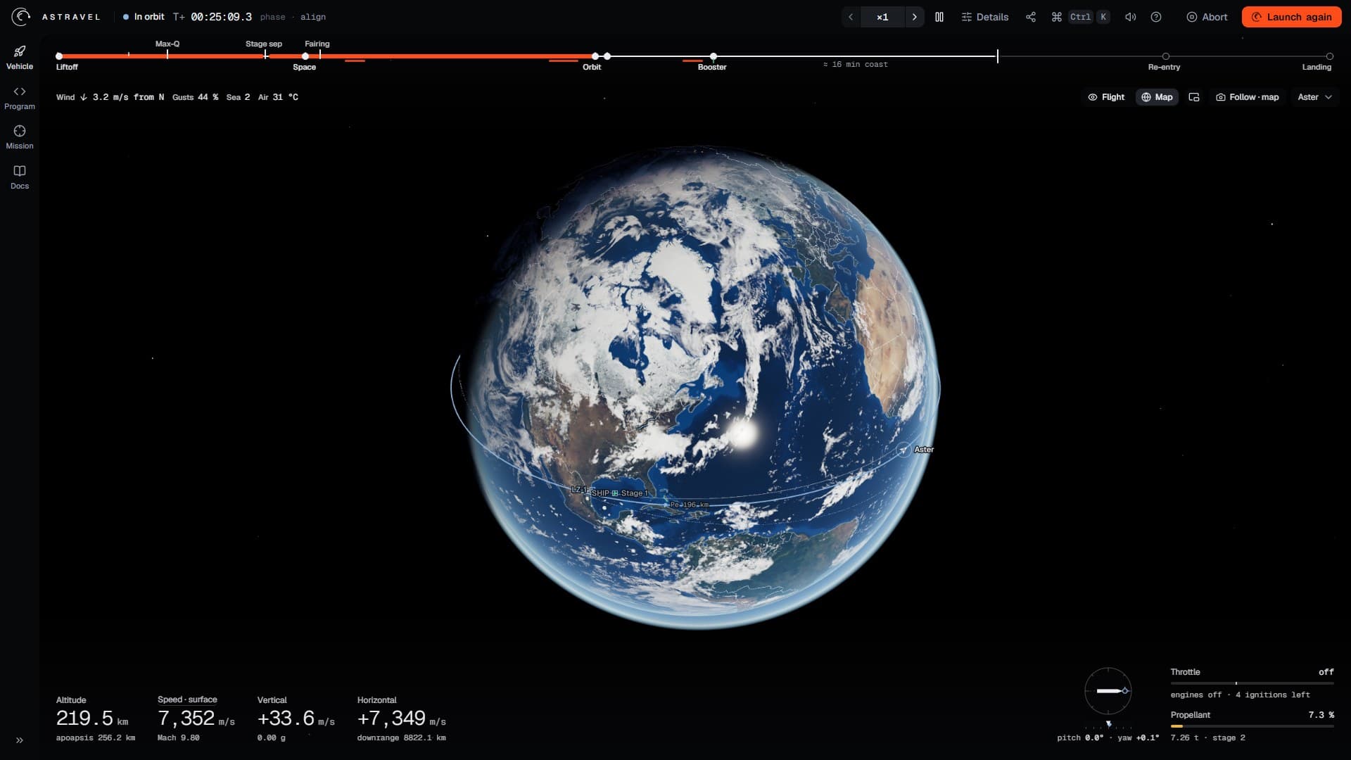
- 1The focused vehicle's orbit.
- 2The vehicle, pointing along its body axis, ringed while in focus.
- 3Periapsis, with its altitude (and apoapsis, when in view).
- 4Sites: the launch site, LZ-1 and the drone ship; the target is filled.
The camera looks at the Earth from above the plane of the focused vehicle's orbit — or, on the pad, the plane it will launch into — so an orbit reads as a flattened ring around the planet. It does not turn with the Earth: the continents drift beneath the orbit as they really do. When you open the map, it frames the planet and the whole predicted path.
On the globe:
- Vehicles are small chevrons pointing along their body axis, labelled. One burning an engine is drawn in the burn colour, one that has landed in green, and one that was lost as a red cross. The one in focus has a ring. Click a vehicle to follow it instead.
- The trajectory of the focused vehicle: the orbit it is on, or the arc it will fly, and the ground track under it — solid where it has been, dashed where it is going. On the pad, the great circle it will launch along.
- Periapsis and apoapsis, marked Pe and Ap with their altitudes.
- Sites, as small squares: the launch site by name, LZ-1 and the drone ship by their short names, the target filled in.
The Labels in the scene setting in the camera menu applies here too: every label, only the target, or none.
Where it will come down
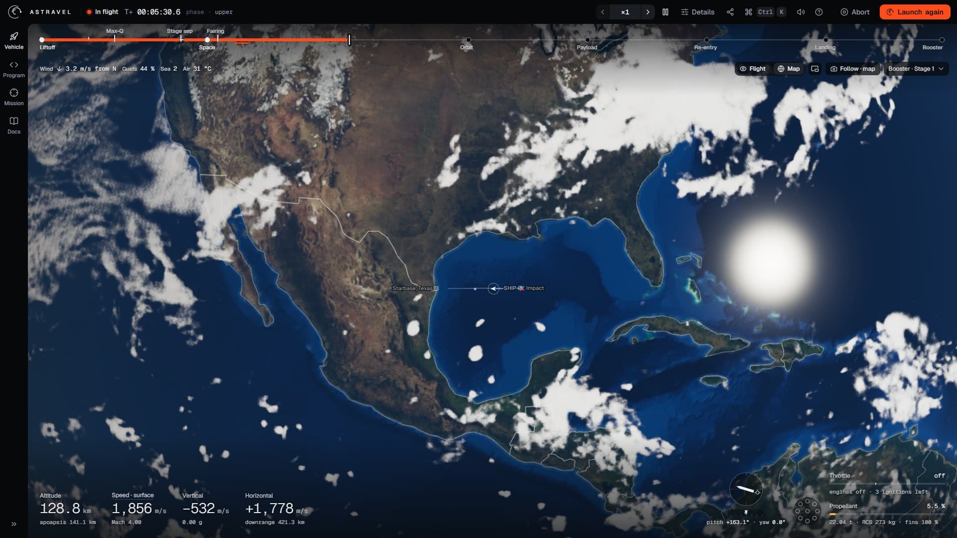
- 1The booster, in focus.
- 2Its predicted path, and the impact point: on the drone ship.
- 3The launch site.
- 4Flight or map.
- 5The vehicle in focus.
For a vehicle that is coming back down, the prediction ends on the ground. The point where the path meets the surface is marked Impact, with a cross, and it is drawn on the ground as it will be when the vehicle gets there — the Earth turns during the fall. Once a landing burn is being planned, a diamond marked Stop shows where that burn will bring the vehicle to rest; it turns red when the burn cannot stop the vehicle in time. The same prediction drives the landing lines of the readouts, described in watching a flight.
Moving around
Drag to turn the view and scroll to zoom; with the view focused, the arrow keys and + / − do the same, and R or a double-click frames everything again. The map zooms towards the centre of the Earth, not towards the vehicle, so to look closely at one region, drag it to the middle first, then zoom in. Zoomed in too far, the camera passes under the surface and the view turns an empty blue: zoom out, or press R.
The inset map
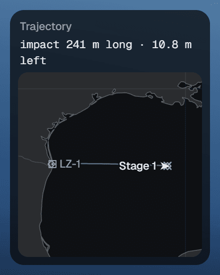
The inset trajectory map keeps a flat map in the corner of the flight view, so that the path and the target stay in sight while the camera is on the vehicle. Turn it on and off with its button among the view tools, or with N. It shows the coastlines and borders, day and night, the ground track behind and ahead, the launch site, LZ-1 and the drone ship, the vehicles and the predicted impact, framed on the flight.
Its header gives the one number that matters on the way down: how far the predicted impact is from the target — long or short along the track, left or right across it. It clears once the vehicle is on the ground. The map shrinks when the window leaves little room, and steps aside altogether when there is none.
Beyond the Earth: the system diagram
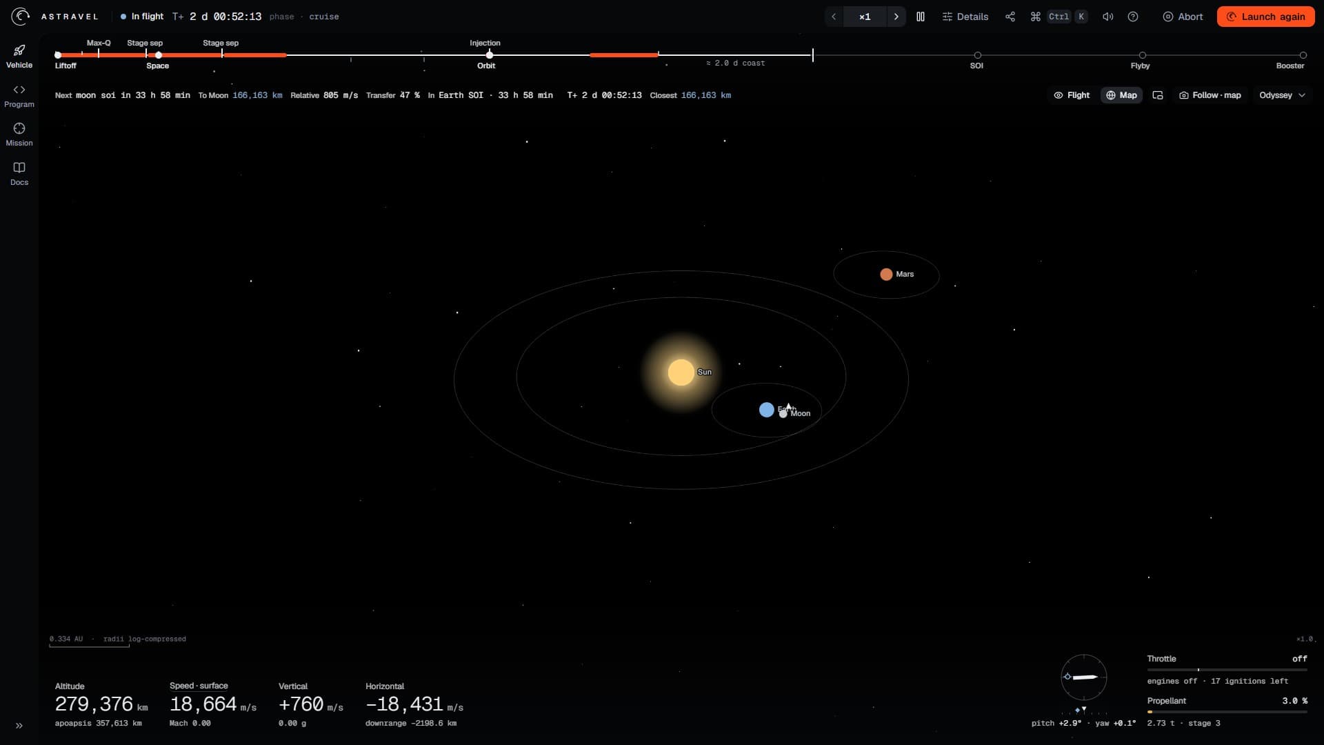
- 1The Sun.
- 2The Earth, the Moon and the vehicle, inside the Earth's sphere of influence.
- 3Mars, with the ring of its sphere of influence.
- 4The scale, and a note while the distances are compressed.
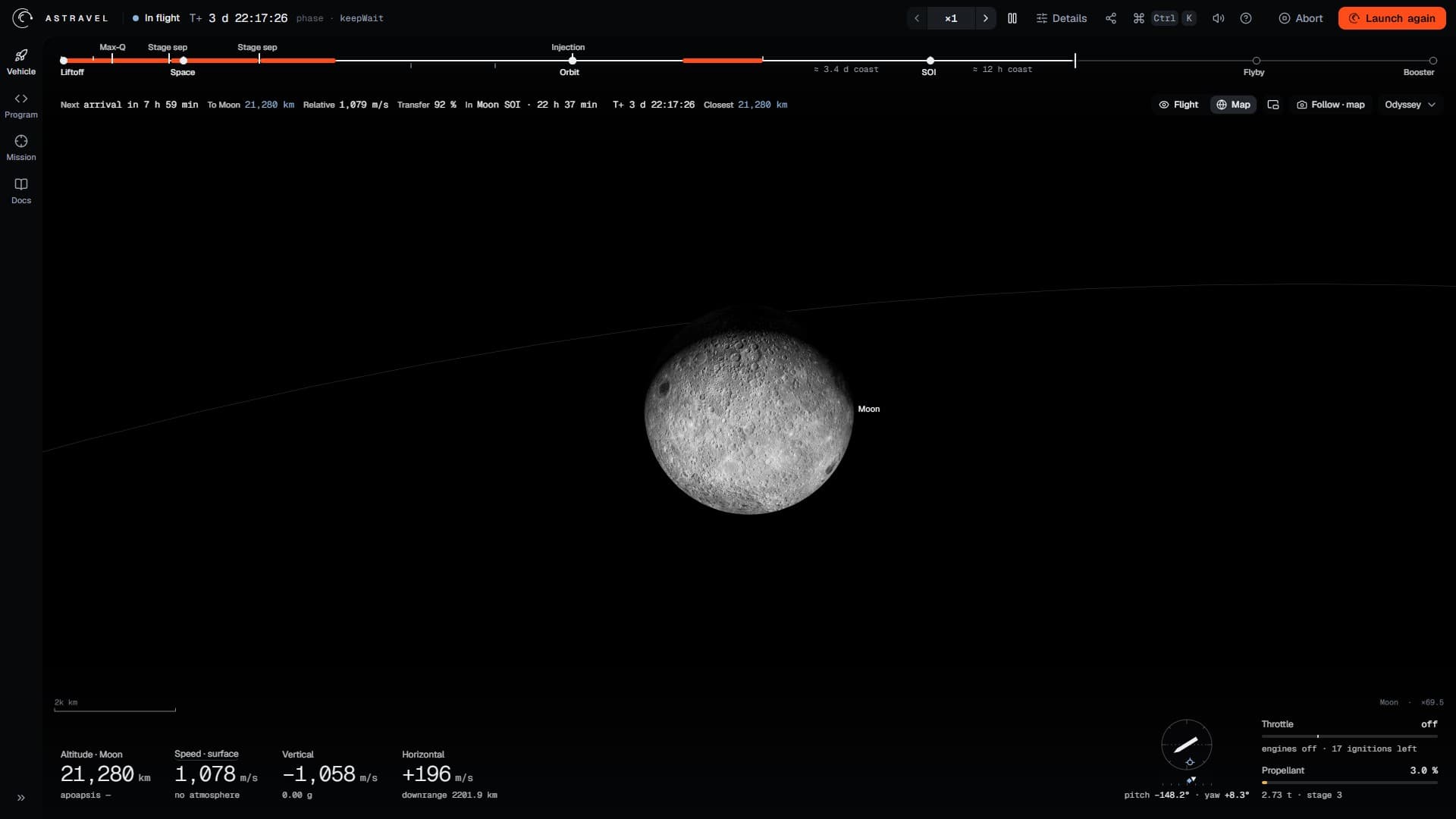
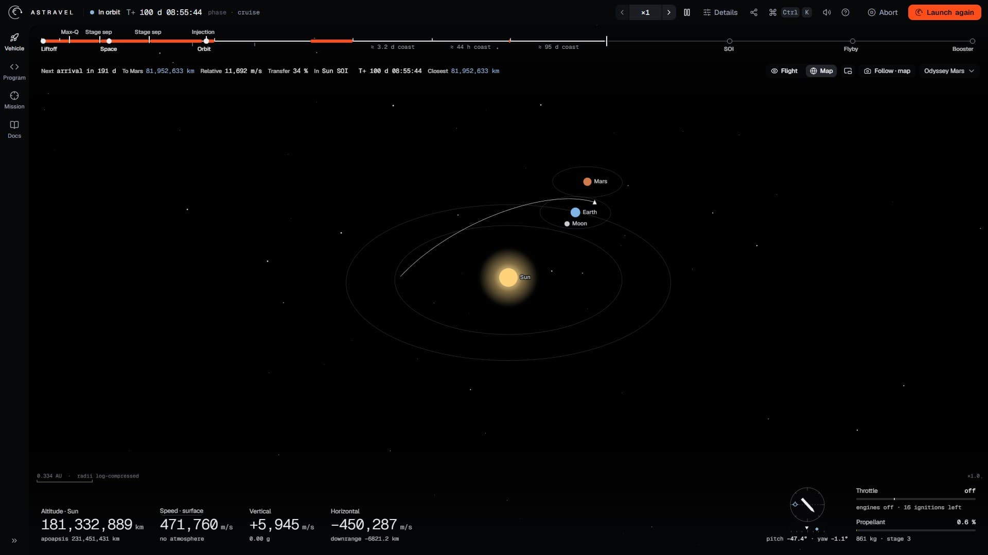
On a flight to the Moon or Mars, the map view draws the Sun, the Earth, the Moon and Mars where they really are on the mission's date, with the vehicle as a small triangle, its transfer arc, and a ring for each body's sphere of influence.
The real distances would leave four invisible dots on a black screen, so the diagram compresses them. A distance from the Sun is drawn on a logarithmic scale, which puts the Earth at 0.69 of the way out and Mars at 0.92, and everything inside a body's sphere of influence — its moon, a vehicle in orbit round it — is spread out on a scale of its own, so that the Moon and a parking orbit show beside the Earth rather than on top of it. The scale bar in the corner says radii log-compressed while this is so.
Zooming into a body
Click a body, in the diagram, and the view centres on it and zooms in until it fills a third of the height. As it does, the compression eases out: past about four times the whole-system zoom the geometry around that body starts to become true, and by forty times it is — the scale bar then gives plain kilometres, and the flat disc of the diagram has faded into a textured globe in the same place. Scrolling in does the same, around whichever body is nearest the middle.
The Moon and Mars are real globes, lit by the Sun from where it really is, with their large features in their real places: the maria and the bright rays of the Moon, and on Mars the dark Syrtis Major, the Hellas basin, the Tharsis volcanoes, Valles Marineris and the polar caps. Drag to go round them, as on the Earth. Double-click empty space, or press R, to go back to the whole system.